
|
The R-390A Frequently Asked Questions Page |
|---|
|
Repairing Mechanical Filters From An R-390A
|
This account applies to the later style of filter where the outer barrel has a matt finish and the coil connections are diametrically opposed. The early type with a shiny barrel has a different form of construction but the principles are similar.
Many of these filters are failing. Apart from the obvious symptom where a filter winding is open circuit, they can also develop a leak to ground which spoils the operation of the AGC.
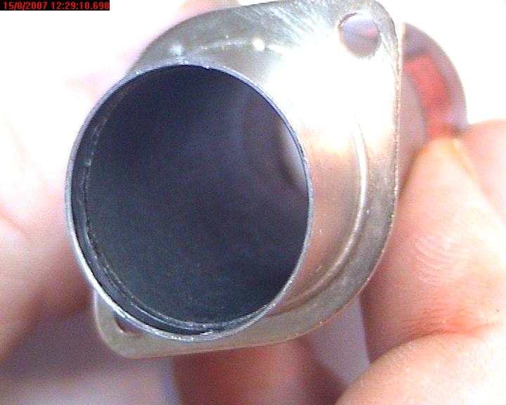
The body of the filter was originally supported within the outer barrel by a combination of stiff paper washers and foam doughnuts. Over time the foam breaks down and turns into a tarry substance which contaminates the filter. The paper becomes very brittle and crumbles.
The result of this is that the mechanical assembly is no longer supported within the case. This can either be bad, or very bad. The mechanical assembly has a flat strip earth wire which is spot welded to the disk assembly, and is also trapped and soldered together with the end cap at the input end (nearest the flange). Once the foam has broken down, the earth wire is the only means of longitudinal constraint. There is no longer any lateral constraint and if you gently shake the filter from side to side you can probably feel the internal assembly flopping around.
Things get very bad when the earth wire breaks. Apart from causing an increase in filter blow-by, the entire weight of the mechanical assembly will now be supported by the leadout wires for the actuator coils. One bump in the right direction and the wire breaks. However, even before this happens, the filter will probably develop a leak to its case. They were originally rated at 300V dc. A leak of a few megohms will disturb the action of the AGC causing overloading on strong signals.
I had three faulty filters in my EAC. I guess I am just lucky like that. I decided to try to get to grips with the problems. I am passing on my experiences so that others will be able to improve upon my techniques and hopefully share their experiences.
Note that I had a filter which was both leaky and with an open-circuit coil. You might choose to be more conservative with your filter overhaul; I had little to lose.
There are three filters posing for photographs; one 16 kHz , one 8 kHz and one 4 kHz. This accounts for the differences in the disk structure between certain photographs. The 16 kHz and the 4 kHz had broken earth wires, the 8 kHz did not. The 16kHz was very leaky. The 8kHz was leaky and open circuit. The only symptom with the 4 kHz filter was blowby. This manifested itself as a vague twittering in the background when listening to SSB.
Repair procedure
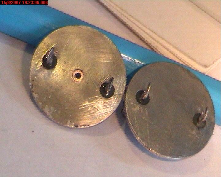
Remove the faulty filter and salvage its mica capacitor. You will notice that the end caps are not identical. The lower cap, which is on the driven end of the filter, has a pinched-off copper tube in the centre. Start by trimming off the pinched end and clearing the hole with a soldering iron or small drill. You are aiming to provide a vent to the atmosphere. I didn't do this to the first filter I opened. I was treated to a hot end cap hitting me in the chest like a rubber bullet!
You will need a source of controllable heat. I used a small butane torch; the type used to flambe tomatos. Hold the filter horizontally by its flange in a vise. We will remove the output cap first (the one furthest from the flange). Try to arrange a metal sheet immediately beneath the filter so when the end cap comes out it has somewhere to land without pulling on the fine wires. I used a spring hook to gently pull the terminal hooks whilst playing the flame in circles around the cap. It is quite possible to do this without burning the label. Once you see the solder start to run, carefully put down the butane torch (something else I didn't do first time round) and then gently pull the cap. It should slide out with little resistance. Let it rest on the tray to cool.
When it is cool enough, snip the two fine wires from the solder tags on the end cap and place the cap out of the way. Turn the filter round in the vise and remove the second cap. This one may be slightly tighter since it should have the earth wire trapped between its periphery and the barrel. Disconnect the wires as before.

Remove the paper insulators from the end caps and examine the caps with an eye-glass. The ones I have examined have had a build-up of conductive detritus around the terminal insulators.
Now is a good time to remove the excess solder from the end caps. Hold each cap in pliers and heat it until the solder runs. With a swift flick of the wrist you can fling off the excess solder. Give some thought to where the solder will go before you do this.
By now the filter will have cooled. You will probably see a dismal black powdery sticky goo.This used to be foam rubber. It is amazing that a substance can be both powdery and sticky. Keep it off your clothes. I scooped most of it out with a spring hook. Carefully withdraw the mechanical assembly.
You will see that the filter comprises a set of disks with a coil at each end. This assembly will almost certainly need to be cleaned. In my case the debris from the foam had gone between the disks. Fortunately it seems to clean off quite well in alcohol. Be careful not to bend any of the coupling rods whilst handling the assembly.
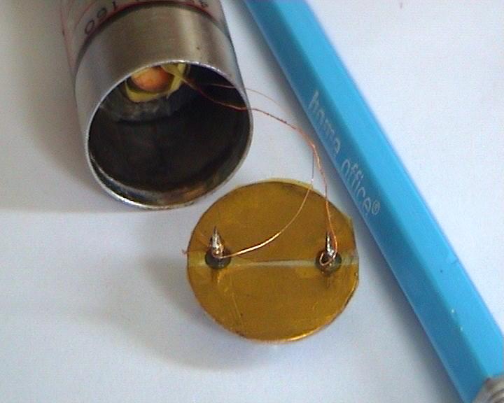
At each end of the filter, there is an actuator coil which sits inside a copper cup. In the centre of the coil there is a very fine magnetostrictive needle. On the outside of the copper cup there is a bias magnet which is both glued and taped in position. I removed the tape and the magnets in order to get the assembly clean.
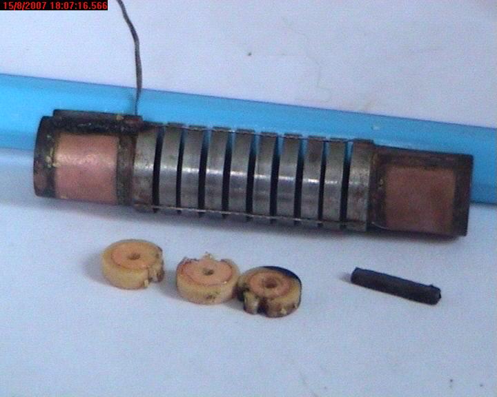
In the foreground of this picture are the three cheek pieces which form part of the coil. More about them later.
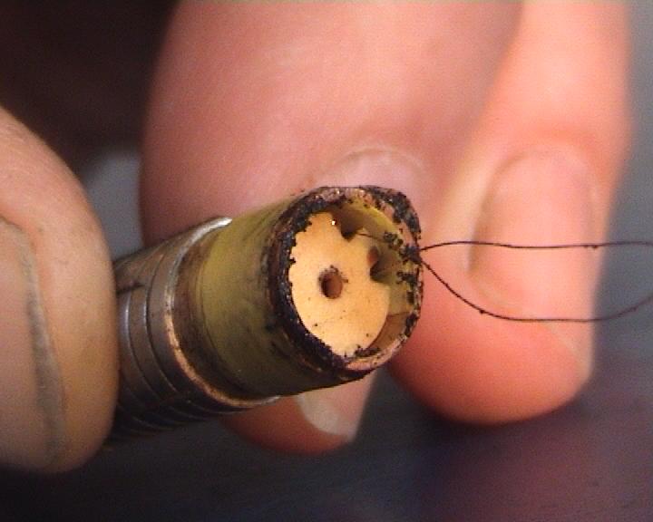
The coils are held in position with a blob of black glue. This can be removed by careful scraping with a pair of tweezers. There is a tail of yellow tape extending longitudinally alongside the coil. If you want to remove the coil, a gentle pull on the tape should do it. If it is reluctant to move you may be able to get it to rotate slightly using a pair of fine pointed tweezers. Be aware that the fine magnetostrictive wire is in the centre of the coil. It should not be in contact with the coil, it is self supporting and closely centred. You must make every effort not to kink it.
Here is a picture of the coil in position. You will also see the bias magnet held to the outside of the copper cup with yellow tape. Note also the helpful tape for withdrawing the coil.
You can just make out the actuator wire in the centre of the coil. Here is a picture of the cup and the actuator wire with the coil removed. You can also see my replacement copper tape earth wire, which I soldered on top of the broken stub of the old one.
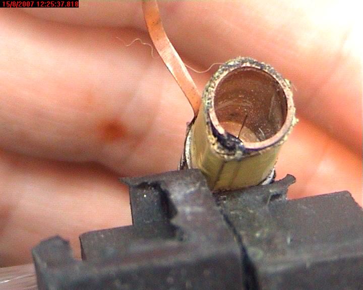
This gives an idea of the delicate nature of the wire. Note for purposes of scale one of my dog's hairs is stuck to the tape! Although you should not bend this wire, if you accidentally do so it can be gently manipulated with hairspring tweezers to get it centred. Use a pulling action rather than a kinking one.
Once the coils were removed I felt it quite safe to ultrasonically clean the filter in isopropyl alcohol. It is important that there should be no debris between the disks. I cleaned between the disks with a sliver of paper, trying hard not to distress the centre wire. The magnets had also collected magnetic debris. This is best removed with a rolled-up piece of sticky tape.
There are two causes of electrical leakage. I had both in the same filter. One is a build-up of conductive rubbish on the glass feedthrough insulators. Needless to say these need to be cleaned until they glisten. The other is more serious and it appears to be a conductive film between the coil winding and the cupper cup. This is presumably a combination of a breakdown of the wire enamel and a contamination of the cheeks. This necessitates rewinding the coil. Since one of mine was open circuit I was already resigned to doing that.
The coil is wound in two sections using three insulating washers, two as cheeks and one as the central partition. There is no coil former; the coil is self supporting. You may want to count the turns on your coil to see if you get the same answer as me. I think there are 610 turns of 0.071 mm (0.003") enamelled copper wire per section. The real interesting thing is that the phase of the coil reverses at the centre. So you wind 610 turns, cross the centre partition and then wind 610 in the opposite direction.
In case you feel the need to make new washers, they are 6.35 mm (1/4") diameter, 1.59mm thick (1/16"), and the holes are 1.1mm ( 0.043"). In any event the washers need to be scraped clean and washed before re-use.
In order to wind a formerless coil, you need to wind it on a mandrel which will be withdrawn when the coil is finished. But this is a tiny job. My first efforts failed because the mandrel damaged the wire as I withdrew it. My friend Mick Bignell, who is famous for thinking out of the box, came up with the answer. Use a piece of PTFE sleeving as the mandrel, but stiffen it with a steel rod up the centre.
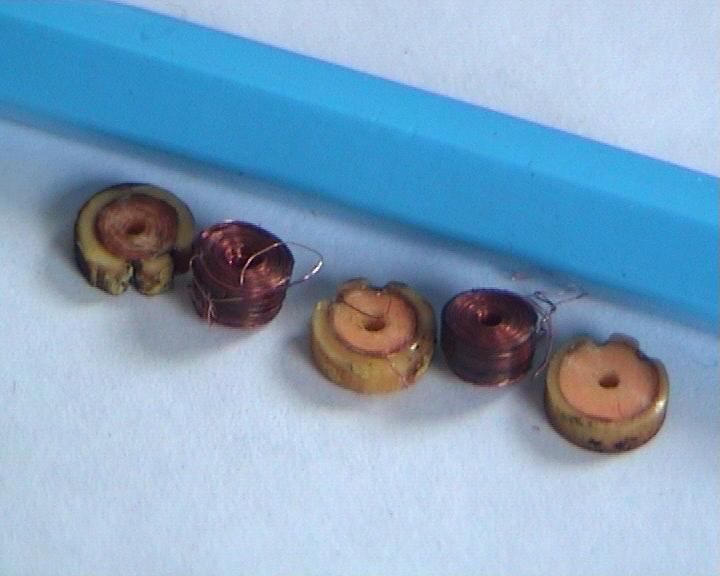
Here you see the three cheek pieces threaded onto the PTFE sleeving. There is a length of blue pivot steel inserted into the sleeving. The pin-vice is gripping the sleeving in order to drive it. Note that the outside distance of the outer cheeks should be about 9.8mm. It is best to err slightly on the tight side since they tend to spread a little when the wire is applied. The centre cheek is centrally disposed between them.
I used a coil winder because I have one; the pin vice was held in the chuck. This job does not need much torque, so an improvised winder and turns counter would do just as well. The wire was guided by hand. I did invest in a pair of surgical loupes. I often work with a watchmakers eyeglass but I got sick of burning my hair with the soldering iron. Plus I am getting old and I need all the help I can get.
The wire used was grade one solderable polyurethane enamelled copper. Polyester enamel would be more thermally robust but slightly harder to solder.
Winding the coil would be much simpler if it were not for the need to keep applying transformer varnish. You must keep doing this so that the inner coils can't cave in. The varnish is also the only thing that holds the end cheeks in position. I tried to keep the coil wet with varnish as I wound it. My air drying transformer varnish comes in an aerosol can. With hindsight I should have decanted a little and applied it with a fine artist's brush. I am in big trouble regarding the shirt!
Don't forget to turn the job round half way through. The little magnetic wire is not working as a piston; it is being alternately stretched by one coil and compressed by the other. I am only guessing but I suspect that the spacing of the two coils is related to half a wavelength of bulk acoustic wave in the wire. So the phase reversal is the key.

Once the coil is finished it should look like this. Give it a few hours for the varnish to get strong enough to hold it all together. A little warmth will facilitate the process. Interestingly, the varnish dries in two stages. First the solvent evaporates. Then the varnish hardens using oxygen as a catalyst. Of course I was impatient!
Affix a tape extracting tag as before, and secure it with one turn of polyester tape. There is only room for one turn and it produces a nice push fit. If, when you try it, it still feels loose place another extracting tag on the opposite side.
Carefully remove the central steel pin from the mandrel. Then ease the sleeving out of the coil assembly. Tin the wires and measure the resistance. 50 to 60 ohms is good. Infinity is disappointing.
When inserting the coils avoid placing any compressive force on the filter as a whole. I found I was able to insert finger nails into the first gap between the disks so I could push against the copper cup assembly without crushing the coupling rods. If you look closely at the following image you will see the rod on the right has a small bulge. This was damage I inflicted but luckily I was able to pull it straight again

When you are happy with both coils, fifty to sixty ohms, no leakage to the metalwork and the little pin just visible in the centre of the hole, it is time to consider reassembly. You will need to replace the supporting doughnuts. I cut a pair from some air-conditioning pipe self adhesive wrap lagging which I had to hand. A neater job would be to slice doughnuts off ready made tubular lagging. I was attracted by the air-con lagging because presumably it is good with extremes of temperature.
Place a doughnut over each copper cup, taking care not to damage the wires.
Clean inside the barrel with tissues moistened with alcohol. If you are fortunate the original piece of rolled up card which is inside the tube will pull out intact. This makes it easy to clean. Also remove the excess solder from the barrel. The last vestiges can be scraped out with the back edge of a blade. Take care not to spoil the label.
Carefully insert the filter assembly into the barrel. I used the spring hook to manipulate the foam rings as it slid down. The correct position is with the mechanical filter roughly at the longitudinal mid-point of the barrel. The foam rings were placed over the coil cups. I tried to avoid any contact between the foam and the filter disks. If you were able to remove the card tube then you can wrap this round the filter assembly and slide the whole lot back in. Mine was too brittle for re-use.
Make sure that the end caps are spotlessly clean, especially around the insulators. I placed a layer of Kapton tape over the internal surface since the original card disks had disintegrated. This was just a precaution to protect the fine wires from heat when re-soldering the case.
Then carefully connect the wires to the tags. Wrap them several times so that they do not disconnect even if the pin is overheated from the outside.
Give it one final test of continuity and leakage before fitting the end caps and re-soldering them. You can do this with a soldering iron if you take your time for it to warm the entire cap. The terminals were in line with the flange mounting holes on my filters. Take care not to trap the wires. I left mine rather long in case any rework was needed. However, no rework was needed and now I am wondering if shorter leads would have improved the ultimate blow-by on account of reduced capacitive coupling.
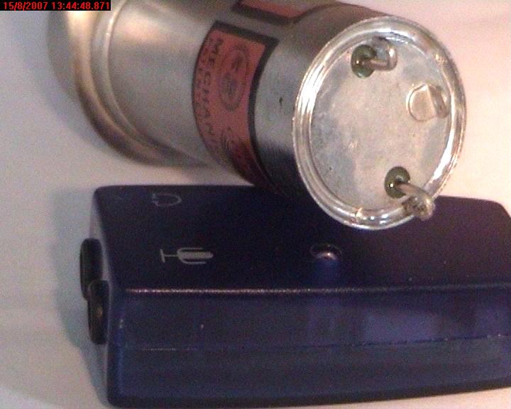
I am quite pleased with the appearance of the resoldered end caps. I think I got lucky!
I measured the leakage with a variable voltage high resistance meter. I was getting better than 200 Megohms at room temperature, measured on the 250 volt range.
When I dismantled the 16 kHz filter, there was a load resistor fitted internally. It was wired in parallel with the coil at the output (topmost) end. The markings had all but gone but I think it was originally 56k. I elected not to refit this. This gave me the option of fitting an external resistor in order to balance my filter gains should the need arise. The 8 kHz filter did not have a resistor.
The filters are now back in the radio. My AGC problems have gone. The filters have slightly ripply flat tops and impressive skirt slopes. I don't know if they are as good as new ones, but they work well and their losses are on a par with the other filters. I am still considering what to do about the capillary tube nipples. Were they originally evacuated or should we vac them down and then flood them with dry nitrogen? Until I find out I am leaving mine open to the atmosphere so that the varnish can well and truly go off.
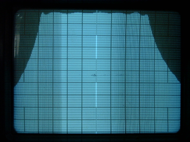
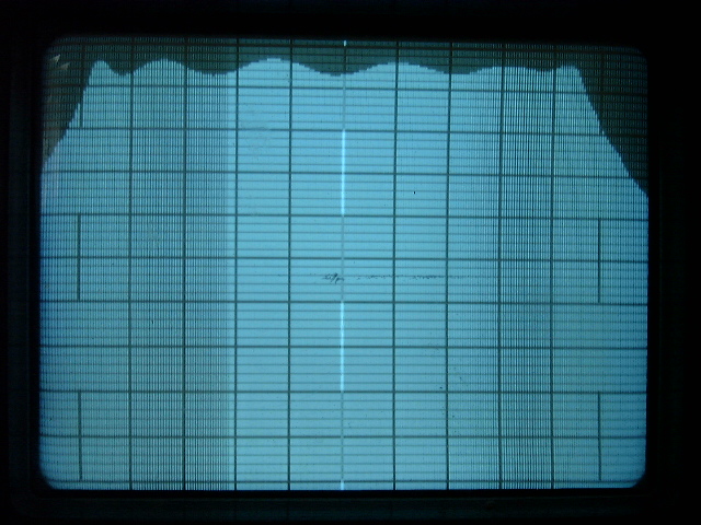
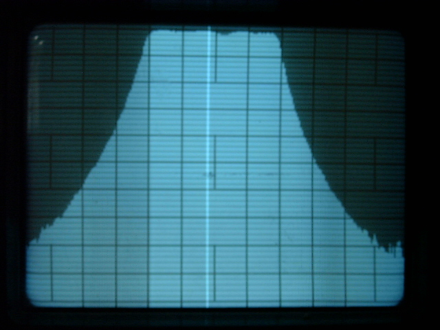
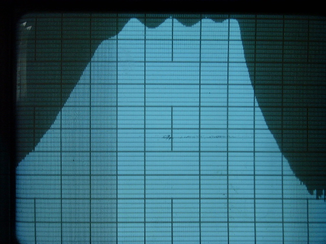
Here are some frequency response plots of the four mechanical filters in the radio. They are all plotted at 10 dB per major vertical division. The 2 kHz filter has not been repaired. It doesn't look right to me!
| 16 k filter | 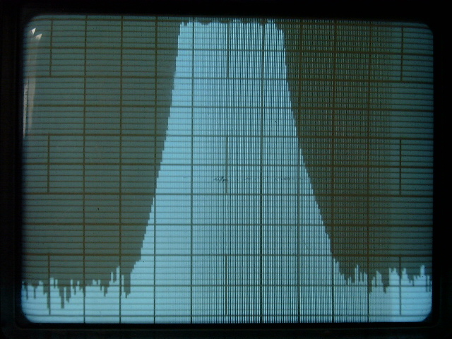 |
 |
| 5 kHz per major horizontal division | 2 kHz per major horizontal division | |
| 8 k filter | 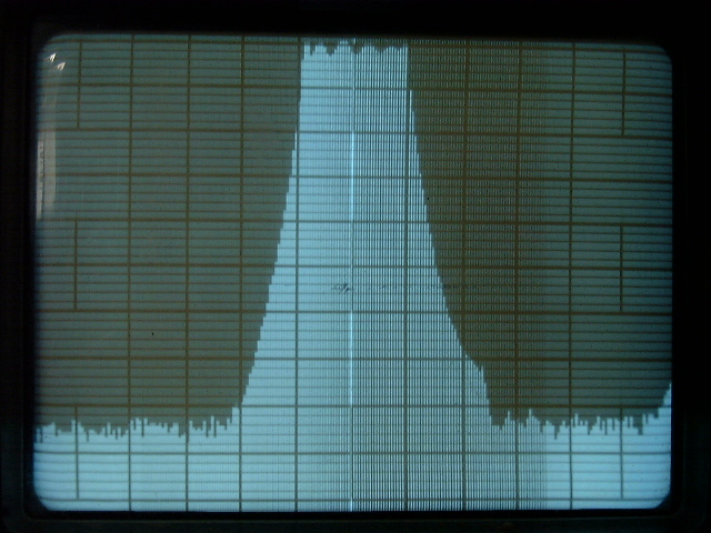 |
 |
| 5 kHz per major horizontal division | 1 kHz per major horizontal division | |
| 4 k filter | 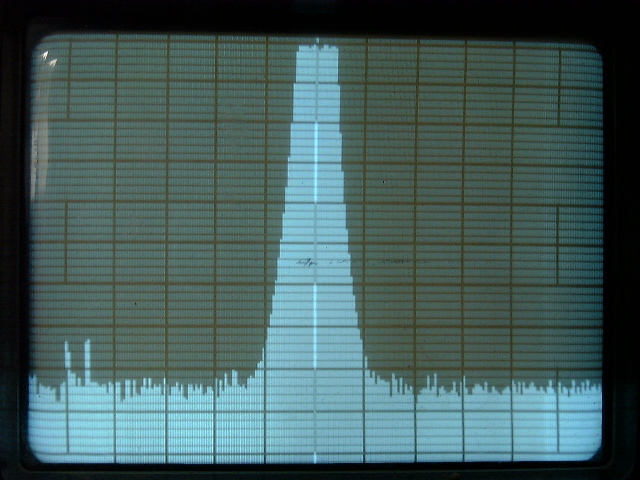 |
 |
| 5 kHz per major horizontal division | 1 kHz per major horizontal division | |
| 2 k filter | 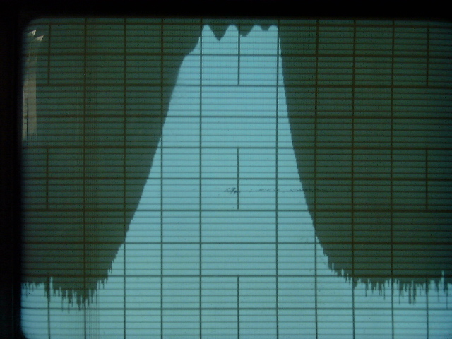 |
 |
| 1 kHz per major horizontal division | 500 Hz per major horizontal division |
In the introduction I mentioned that the early type of filter has a different mechanical construction. With this type, you proceed in a similar manner, but you need to heat both end caps at once. The entire assembly withdraws from the barrel from either end. The two end caps are attached to each other internally by a metal frame. The filter mechanism lies within this frame and can then be removed.
Good luck with your efforts!
|
Send Comments to the FAQ-Meister: (root[at]r-390a[dot]net) |
|||
|
Version: 3 - - Last revision: 2007-Sep-03 |
|---|